Introduction
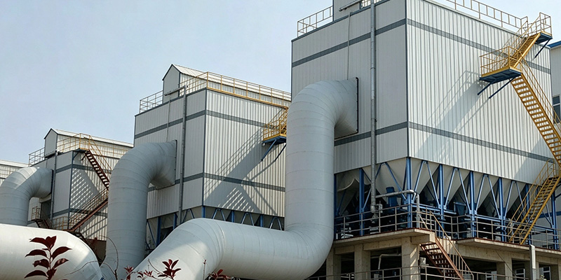
The discharge point is the least discussed and most frequently neglected part of a dust collection system. Engineers spend weeks on air-to-cloth ratio, filter media and cleaning cycles, then specify the ash discharge device from a catalogue in ten minutes.
That device decides whether the collector keeps working. A discharge that leaks air reduces the effective airflow through the bags, raises the air-to-cloth ratio, and causes premature bag failure. A discharge that cannot keep up with the dust load backs material into the hopper, bridges over the outlet, and eventually forces the collector offline.
This guide compares the three devices used under cement plant dust collectors — rotary valve, double flap valve and screw conveyor — on how they seal, what they handle, where they fail, and how to size them.
1. Short Answer
| Situation | Recommended discharge |
| Continuous dust flow, negative pressure collector, fine powder | Rotary valve |
| Intermittent discharge, coarse or fragile material, limited maintenance access | Double flap valve |
| Material must be transported horizontally to a silo or another point | Rotary valve plus screw conveyor |
| High temperature ducting with coarse ash and low discharge frequency | Double flap valve plus short screw |
| Sticky, damp or highly hygroscopic dust | Rotary valve with scraper or oversized inlet, heat tracing if required |
The rule that matters most: a screw conveyor does not seal against negative pressure. It transports. The sealing device must be a rotary valve or a double flap valve upstream of it.
2. Why the Discharge Device Decides Collector Performance
Three failure chains start at the discharge:
- Air leakage.Every cubic metre of air pulled through the discharge is air that does not pass through the filter bags. Airflow at the bags drops, the air-to-cloth ratio rises, and the cleaning system starts over-working. The visible result is rising differential pressure and shortened bag life.
- Discharge capacity shortfall.If the valve cannot remove dust as fast as it arrives, material accumulates in the hopper. Once the dust level reaches the inlet, re-entrainment begins and the collector effectively stops separating.
- Bridging and blocking.Damp dust, coarse particles or oversized lumps jam the inlet of the valve. The hopper fills, the operator opens a inspection door, and dust escapes into the plant.
All three are design errors, not operating accidents. Each is prevented by matching the device to the dust, the pressure and the discharge rate.
3. Rotary Valve
3.1 How It Works
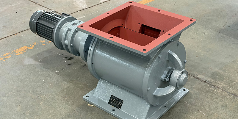
A rotary valve (also called a rotary airlock or star valve) has a rotor with 6–12 pockets turning inside a close-fitting housing. Dust fills the pockets at the top, the rotor carries it past the sealing edge, and it drops out at the bottom. The clearance between rotor tip and housing provides the seal.
3.2 Strengths
- Continuous discharge.Material leaves at a steady rate, which suits collectors running at constant load.
- Fits directly under the hopper outlet with minimal height.
- Wide capacity range.Throughput is controlled by rotor speed, so one body size covers several duties.
- Handles fine, free-flowing dust well.Cement kiln dust, clinker dust and coal mill dust are typical applications.
3.3 Limits
- Leakage rises with wear.The rotor tip clearance grows, and leakage increases accordingly. A worn valve can pass several times the air of a new one.
- Shear risk.The rotor edge can crush fragile material and damage coarse lumps.
- Not suited to sticky dust.Wet or hygroscopic dust packs into pockets and blocks the inlet.
- Temperature limit.Standard valves use rubber or fabric seals rated around 80–120 °C; high-temperature service needs special seals and clearances.
3.4 Selection Points
| Parameter | Guidance |
| Capacity | Size for 1.2–1.5 times calculated dust flow |
| Rotor speed | 15–30 rpm typical; higher speed raises capacity but increases wear and leakage |
| Volumetric efficiency | Allow 75–85% fill for fine dust |
| Clearance | 0.05–0.15 mm new; monitor as part of maintenance |
| Body material | Cast iron standard; wear-resistant or stainless for abrasive or corrosive dust |
| Drive | Direct-coupled gear motor; variable speed for turndown |
| Accessories | Chain sprocket guard, shear pin or torque limiter, inspection cover |
Rotary valve maintenance is predictable: clearance check, seal replacement and rotor inspection. The rotary airlock maintenance guide covers the intervals and the wear limits.
4. Double Flap Valve
4.1 How It Works
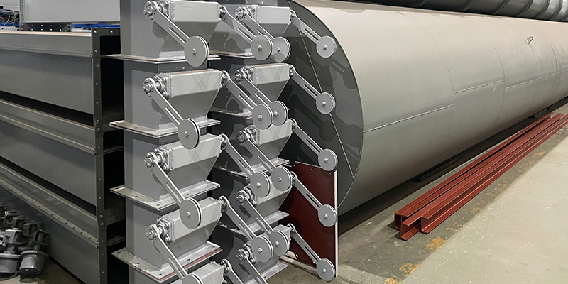
A double flap valve uses two hinged plates stacked in a housing. The upper flap opens under the weight of accumulated dust and closes; the lower flap then opens and discharges. The two flaps never open at the same time, so the seal is maintained by the closed plate rather than by a clearance.
4.2 Strengths
- Effective seal at negative pressure.No continuous leakage path exists; leakage occurs only during the brief opening cycle.
- No shear.Coarse lumps and fragile material pass without being crushed.
- Low power demand.Operation is gravity-driven, with only a small actuator on some designs.
- Tolerant of coarse ash.Suitable for clinker dust, broken bags and agglomerated material.
4.3 Limits
- Intermittent discharge.Material leaves in batches, so the hopper must buffer between cycles.
- Frequency ceiling.Above roughly 10–15 cycles per minute the flaps do not close reliably and the seal degrades.
- Damp or sticky dust holds the flaps open, which creates a permanent leakage path.
- The stacked housing needs more vertical space than a rotary valve.
4.4 When to Choose
Use a double flap valve when the collector runs under negative pressure, the material is coarse or fragile, discharge is intermittent, and maintenance access is limited. It is the standard choice under small and medium baghouses where a rotary valve would be over-specified. For a direct comparison of the two sealing devices, see the double flap valve versus rotary airlock analysis.
5. Screw Conveyor as the Discharge Conveyor
5.1 Role
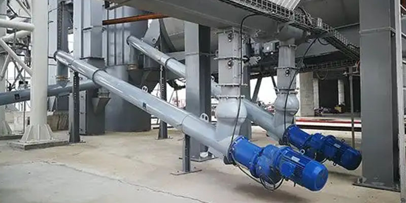
A screw conveyor moves material horizontally or at a slight incline. It is a transport device, not a pressure seal. Installed directly under a negative-pressure hopper without an upstream airlock, it draws air along the trough and defeats the collector.
5.2 Correct Application
- Downstream of a rotary valve or double flap valve, carrying dust to a silo, a mixing point or another conveyor.
- Collecting from several hoppersinto one transport line.
- Short runsup to roughly 20–30 m, with limited inclination.
Sizing follows the same logic as any screw: capacity, trough loading, screw diameter, pitch, speed and material class. Cement dust typically runs at 15–30% trough loading with a standard-pitch screw.
6. Comparison
| Factor | Rotary valve | Double flap valve | Screw conveyor |
| Primary function | Seal and meter | Seal only | Transport only |
| Air leakage | Continuous, increases with wear | Only during opening cycle | Not a sealing device |
| Discharge pattern | Continuous | Batch | Continuous |
| Coarse or fragile material | Shear risk | No shear | Moderate, depends on clearance |
| Sticky or damp dust | Packs into pockets | Holds flaps open | Builds on flights and trough |
| Temperature capability | Limited by seals, 80–120 °C standard | Higher, limited by flap and hinge | Higher, limited by bearings and hanger |
| Power demand | Moderate | Low | Moderate to high |
| Vertical space | Low | Moderate to high | Low, but horizontal length |
| Maintenance focus | Clearance, seals, rotor | Flap seat, hinge, counterweight | Flights, hanger bearings, trough wear |
| Typical use | Continuous fine dust | Intermittent coarse ash | Transport after sealing |
7. Typical Configurations
| Configuration | Layout | Best for |
| Single rotary valve | Hopper, valve, direct to silo or truck | Small collectors, short discharge runs |
| Rotary valve plus screw | Hopper, valve, screw, silo | Multiple hoppers feeding one transport line |
| Double flap plus screw | Hopper, flap valve, screw, silo | Coarse ash, negative pressure, low frequency |
| Two rotary valves in series | Hopper, valve, valve, transport | High negative pressure where single-valve leakage is unacceptable |
| Rotary valve with variable speed | Hopper, VFD-driven valve, transport | Loads that vary widely through the day |
Series valves are used where the pressure differential exceeds what one valve can seal, or where leakage must be minimised because the collector is close to its airflow limit.
8. Sizing the Discharge
The valve must handle the dust the collector actually collects, not the nominal dust load on the drawing.
Step 1 — Calculate collected dust.
Dust rate (kg/h) = gas flow (m³/h) × inlet dust concentration (g/m³) × collection efficiency ÷ 1000.
Worked example: 100,000 m³/h, 50 g/m³ inlet concentration, 99.5% efficiency.
Collected dust = 100,000 × 50 × 0.995 ÷ 1000 = 4,975 kg/h, approximately 5 t/h.
Step 2 — Apply a margin. Size the device for 6–7.5 t/h, that is 1.2–1.5 times the calculated rate, to absorb peaks and avoid hopper accumulation.
Step 3 — Convert to valve capacity. For a rotary valve: capacity (t/h) = pocket volume (L) × speed (rpm) × 60 × bulk density (t/m³) × volumetric efficiency ÷ 1000.
Example: 8 L per revolution, 25 rpm, 1.0 t/m³ bulk density, 80% volumetric efficiency gives 9.6 t/h, adequate for a 5 t/h duty with margin.
Step 4 — Check the constraints. Verify temperature against seal rating, abrasion against body material, and pressure differential against seal type. For high differential pressure, confirm with the supplier rather than extrapolating from a catalogue.
9. Common Problems
| Problem | Likely cause | Corrective action |
| Rising differential pressure, dropping airflow | Valve leakage from worn clearance | Check clearance, replace rotor or housing liner |
| Hopper fills despite valve running | Undersized valve, blocked inlet, wrong speed | Recalculate duty, clear inlet, adjust speed |
| Dust escaping at the discharge | Seal failure, flap held open, missing gasket | Replace seal, clean flap seat, inspect gasket |
| Motor overload trips | Material jam, oversized lumps, bearing failure | Add a screen or lump breaker upstream, inspect bearings |
| Sticky dust blocks pockets | Damp dust, condensed moisture | Heat the hopper, use a scraper rotor, reduce moisture at source |
| Screw conveyor floods | No upstream airlock, overloading | Install a rotary valve or flap valve upstream, reduce trough loading |
| Flap valve cycles continuously | Leakage past seat, counterweight wrong | Reseat the flap, adjust counterweight, check for obstructions |
10. Selection Checklist
| Question | Implication |
| Is the collector under negative pressure? | A sealing device is mandatory; a screw alone is not acceptable |
| Is discharge continuous or intermittent? | Continuous favours a rotary valve; intermittent allows a flap valve |
| Is the dust fine and free-flowing, or coarse and fragile? | Fine favours a rotary valve; coarse or fragile favours a flap valve |
| What is the dust temperature? | Above 120 °C requires high-temperature seals or an all-metal valve |
| How much vertical space is available? | Flap valves need more height than rotary valves |
| Must the dust be transported after discharge? | Add a screw conveyor downstream of the sealing device |
| Is the dust combustible? | Use an explosion-rated valve with appropriate clearances and bonding |
11. FAQ
Q1: Can I use only a screw conveyor under a baghouse?
No. A screw conveyor does not seal against negative pressure. Air will flow along the trough into the collector, reducing airflow through the bags and raising the air-to-cloth ratio. A rotary valve or double flap valve must be installed upstream.
Q2: Which device leaks less, a rotary valve or a double flap valve?
A double flap valve leaks less in principle, because the closed plate provides a positive seal and leakage occurs only during the opening cycle. A rotary valve leaks continuously through the tip clearance, and leakage increases as the valve wears.
Q3: Why does my rotary valve leak more than it used to?
Rotor tip clearance has increased through wear. A new valve runs at 0.05–0.15 mm clearance; after months of abrasive dust the gap widens and leakage rises with it. Replacing the rotor or the housing liner restores the original performance.
Q4: Can a rotary valve handle hot dust from a kiln?
Standard seals are rated around 80–120 °C. Above that, specify high-temperature seals, increased clearance to allow for thermal expansion, and a suitable bearing arrangement. Confirm the actual dust temperature, not the gas temperature at the inlet.
Q5: How often should the discharge device be inspected?
Monthly for clearance and seal condition on a rotary valve; quarterly for flap seats and hinges. Weekly checks of hopper level and motor current catch most developing faults earlier than a scheduled inspection.
Q6: Is a variable-speed rotary valve worth it?
Yes where the dust load varies significantly, for example a kiln bypass or a mill that runs part-time. Reducing speed during low-load periods cuts wear and leakage without affecting discharge.
12. Conclusion
The discharge device is a sealing decision first and a conveying decision second. Under a negative-pressure collector, choose a rotary valve for continuous fine dust and a double flap valve for intermittent coarse ash; add a screw conveyor only to transport material after it has been sealed.
Size the device from the calculated dust rate with a 1.2–1.5 margin, then verify temperature, abrasion and pressure differential against the actual duty. Most discharge problems in cement plants trace back to one of these three checks being skipped at the design stage.
Need help specifying a discharge arrangement for your collector? Contact Darko Cement with the gas flow, inlet dust concentration, dust temperature and discharge destination, and our engineers will size the valve and conveyor combination. Review our dust collector discharge system range, the rotary valve and flap valve product lines, and the tubular screw conveyor series.