

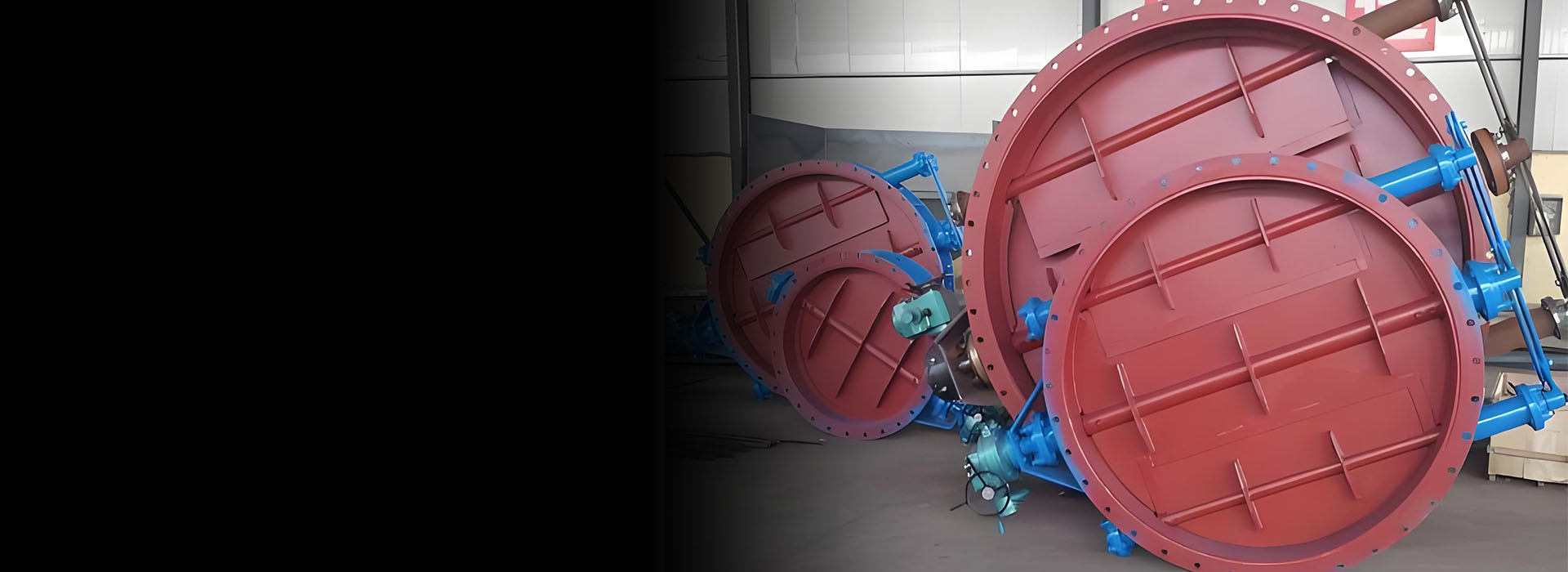
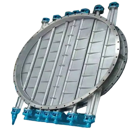
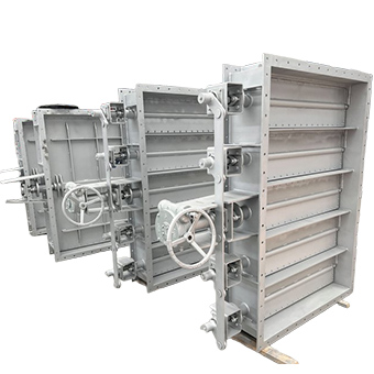
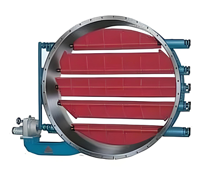
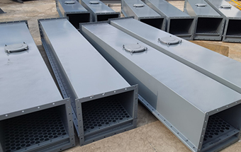
Louver Damper
- Bolted dual airfoil design to minimize deflection and warping of blades.
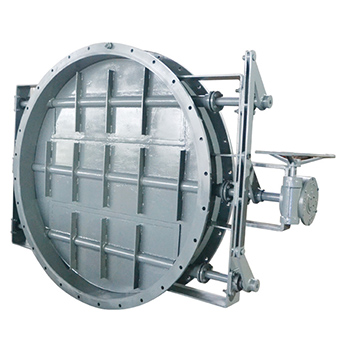
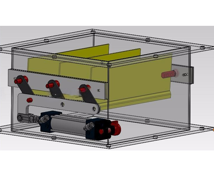
- Electric, pneumatic, hydraulic, or manual actuation.
- Outboard bearings to prevent flue gas exposure and allow for ambient cooling.
- Bearings are permanently sealed and lubricated to eliminate maintenance.
- Bolted packing gland assembly at damper shafts for ease of maintenance.
- Blade to blade, top & bottom, and jamb seals are available to minimize leakage to less than 1% of flow volume.
Benefits of Choosing Darko’s Louver Dampers
Every louver damper undergoes factory operational testing and calibration prior to shipping, ensuring reliable performance right out of the box. And with direct access to knowledgeable professionals, customers enjoy quick answers, informed decisions, and responsive support without the hassle of corporate red tape.
What is a Louver Damper?
A louver damper is a device that has horizontal blades that rotate on a fulcrum in order to control the flow of materials. These dampers are able to offer precise flow regulation with little to no leakage, depending on the design. Single and double louver designs are available in order to offer varied levels of control over air flow. Different types of blades are often used as well for applications with various temperature needs or types of gas being ventilated.
Louver dampers work in three basic steps: controlling airflow, preventing backflow, and regulating pressure.
1. Controls Airflow
Louver dampers control the airflow within a pipeline or ductwork system. This is achieved by adjusting the angle of the blades to their axis, creating more or less space for air to pass through. The degree of blade tilts determines how much air flows through the damper at any given time, making it possible to adjust airflow rates according to specific process requirements.
2. Prevents Backflow
Airflow reversal can occur when there is negative pressure in the system, causing air to move in the opposite direction than intended. Louver dampers ensure that airflow is restricted from moving backward into a system once it has already left it.
3. Regulates Pressure
By adjusting the angle of the blades within the damper assembly, operators can control how much gas flows through a system at any given time. Controlling how much air enters each zone helps maintain consistent pressure levels throughout the system. Maintaining stable pressure levels is paramount for optimal performance in various industrial processes such as power generation, heating, ventilation, and air conditioning.
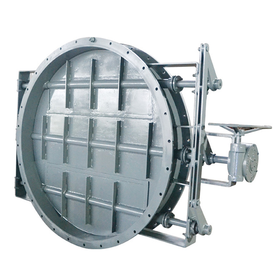
Louver Damper by Features
The key advantages of the louver damper include its fast operating speed and minimum perimeter clearance requirements. Typical heavy duty applications include: Flue Gas processing, component of CHP (combined Heat and Power) diverter system, pressure relief, airflow control, gas exhaust, and pre-spinning of duct air.
Simple structure, without additional driving components, and lower cost.
Dependent on manual adjustment, the adjustment accuracy is relatively low.
Precise flow control over the opening degree (such as a linear adjustment range of 0-100%).
Suitable for large industrial systems, high-temperature/high-pressure environments.
Designed specifically for high-temperature resistance up to 900℃.
Key Features & Specifications
Darko’s industrial louver dampers are built with performance and flexibility in mind.

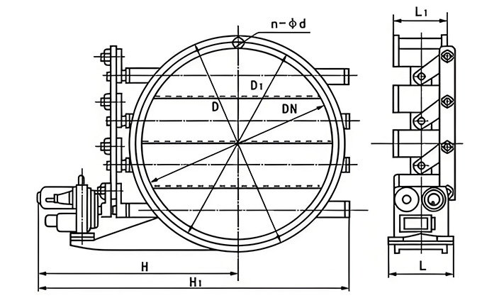
DN350 to DN4500mm

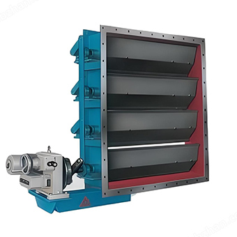
Round, square, or rectangular

Stainless steel and painted carbon steel

Manual, electric, or pneumatic

Handles process temperatures up to 1200 ℃

The service life can reach more than 10 years.

Up to 99%

Modulating or full shutoff capability
Flexible flow regulation
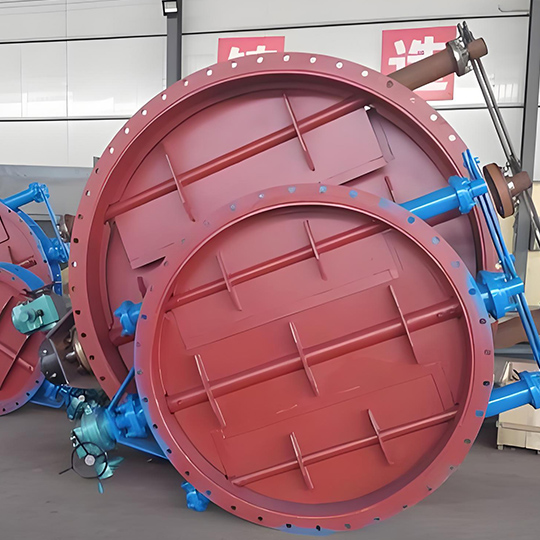
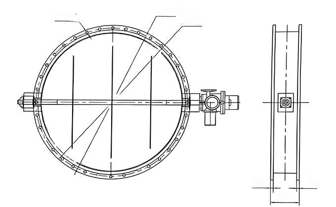
Dako’s louver damper adopts a split-type blade structure. It can synchronously control multiple louvre plates to rotate through a handle or an actuator, enabling continuous angle adjustment ranging from 0 to 90 degrees.
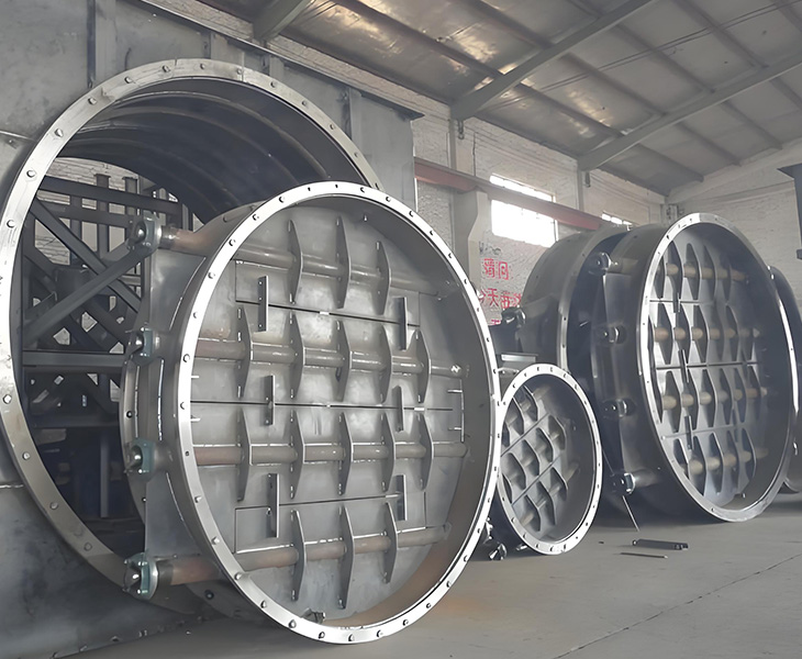
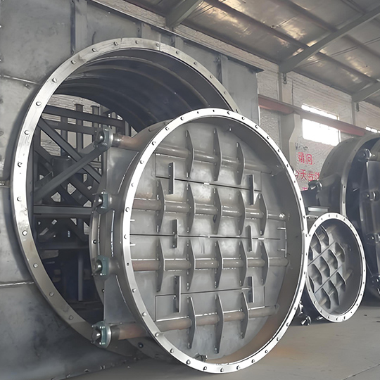
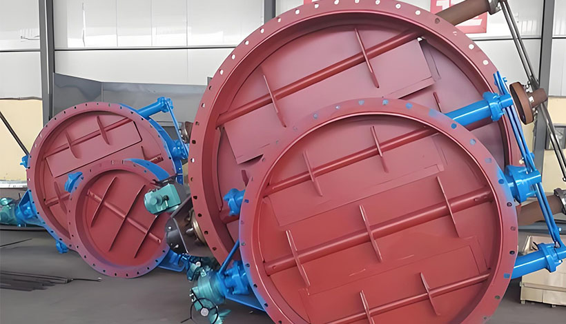
Large-size adaptability
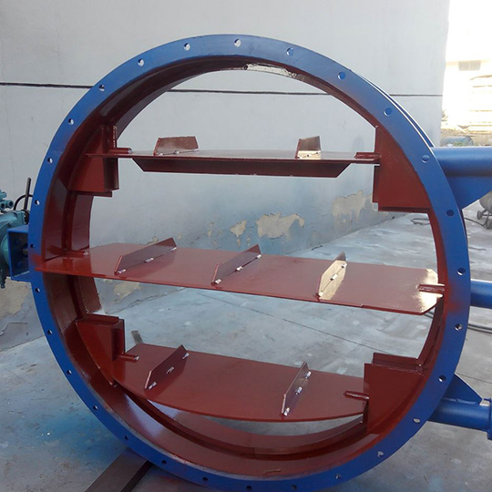
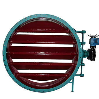
The louver damper is designed with multiple plates rotating around independent axes. It achieves synchronous control through a linkage mechanism to ensure consistent operation of large-sized valves. The maximum diameter can reach over DN4500, meeting the requirements of large pipelines in industries such as metallurgy and power.
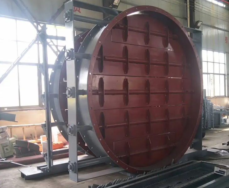
Dust Resistance Performance
The louver damper adopts a design of multiple baffle plates rotating around an axis. Through decentralized transmission, it reduces the impact of dust accumulation on the rotating mechanism. Darko’s electric circular louver damper, with its multi-axis linkage design, can still operate reliably even when the dust concentration in the construction materials industry reaches 200g/m³.
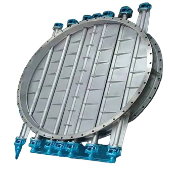
Low-resistance design
The louver damper adopts a multi-leaf rotating design around an axis. The blades have a streamlined structure, effectively reducing turbulence and pressure loss when gas passes through. The flow resistance coefficient is over 30% lower than that of similar valves, and it is particularly suitable for large-diameter (DN3000 and above) and high-flow conditions.
Wide Application of Louver Damper
The louver damper, due to its structural features and regulating performance, is widely used in the industrial field.
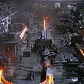
The louver damper is used for rapid shut-off of gas pipelines in the metallurgical industry. The response time is less than 2 seconds. The valve body is mostly made of high-temperature resistant stainless steel or welded carbon steel structure.
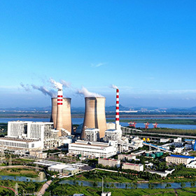
In the desulfurization and denitrification process of power plants, the louver damper regulates the flue gas flow through the synchronous adjustment of multiple blades, and works in coordination with the SCR denitrification device to achieve the reduction of nitrogen oxides.
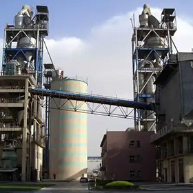
The louver damper is usually installed in the ventilation pipelines of the dust collectors at the top or bottom of the kiln, as well as in the raw material homogenization silos, etc. It regulates the flow of dust-containing gas and reduces the system resistance.
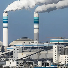
For combustible gas pipelines (such as hydrogen and methane), explosion-proof electric louver dampers are adopted, and the safety shut-off is achieved through ATEX-certified actuators to prevent re-ignition or explosion.
Louver Damper VS Butterfly Valve
Butterfly Valves and louver dampers both are used to manage the free flow of air but with different purposes. People often get confused between louver dampers and butterfly valves due to a few of the similarities they have. For instance, they both have exterior frames and horizontal blades. Moreover, they are mostly placed on walls and can work as either the supply or exhaust entry point for the ventilation system.
- It is composed of multiple independently rotating slats, and the angle is adjusted through a connecting rod mechanism or an electric motor. It belongs to a multi-axis overlapping plate structure.
- The louver damper can continuously adjust the angle of the blades, making it suitable for precisely controlling the flow rate and distributing fluids in multiple directions.
- The butterfly valve uses a single disc-shaped valve plate (in the form of a butterfly wing) and achieves opening and closing by rotating the valve stem by 90°. The structure is simpler and more compact.
- Although the butterfly valve can partially open to regulate the flow rate, its accuracy is relatively low. It is more suitable for quick shut-off operations that require full opening or full closing.
Related Products
-
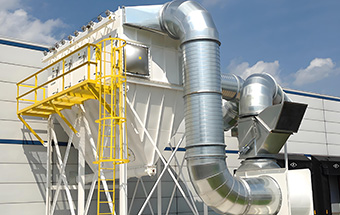
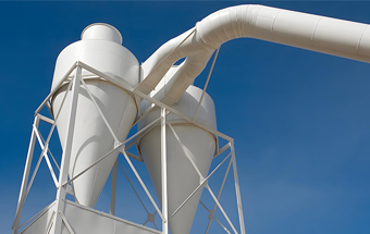
The dust removal efficiency is over 99%, capable of capturing particles larger than 0.3 micrometers.
-
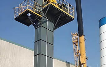
High conveying capacity (up to 800 m³/h) and high lifting height (some models can reach 80 meters).
-
Integrate crushing, drying, grinding, classification and conveying functions.
-
Frequently Asked Questions
When choosing a louver damper, you may have the following concerns and questions. We provide you with detailed answers to help you make an informed decision.
Check whether the zero position of the electric actuator has been adjusted properly. If the valve plate is severely worn and needs to be replaced
It is usually 1 year, but for some special products, it can be up to 2 years.
First, check if the valve shaft flat key or connecting pin has come off;
Second, check if there are any foreign objects blocking the valve plate in the pipeline.
When operating manually, turn the handwheel clockwise to open and counterclockwise to close. Do not use an auxiliary lever.
- Sealing performance: Leakage rate ≤ 3% (for standard type), ≤ 1% in harsh conditions.
- Drive method: Electric (220V/380V), pneumatic (0.5MPa), or manual as backup.
- Actuator selection: Choose DKJ series or MQGB series based on torque requirements.