Dust accumulation on the impeller inside the fan casing is very common in cement plant fans. This has the greatest impact on the fan’s dynamic balance. It relates to the conveying efficiency of the pneumatic conveying system and the service life of the fan.
In cement circulating fans, impeller dust accumulation mainly relates to the fan’s structure, the dust content in the airflow, the flow velocity, and the properties of the material.
Correctly selecting the fan, increasing the inlet box velocity, reducing the fan operating speed, and changing the blade profile design method are effective ways to reduce impeller dust accumulation in cement plant fans.
Introduction
On cement production lines, when we inspect field fans, we find large amounts of dust accumulated inside the casing. This is especially true at the bottom of the inlet box, the bottom of the volute, and on the impeller. Because high-temperature fans, circulating fans, and cement mill circulating fans operate continuously, they constantly convey dust-laden gas. Consequently, dust adheres to the back of the impeller and accumulates more and more.
Dust accumulation on the impeller inside the casing has the greatest impact on the fan’s dynamic balance. Once too much dust accumulates, it causes a decrease in the conveying efficiency of the pneumatic system and abnormal fan vibration. In severe cases, increased fan vibration can damage the bearings. This article takes the cement mill circulating fan system as an example. It analyzes the causes of fan impeller dust accumulation and proposes improvement measures.
1 Problems with the Cement Mill Circulating Fan
A cement grinding system is equipped with a roller press 180×160, a ball mill Φ4.2m×13m, a static separator V5000, a dynamic separator M5000, a cyclone dust collector 2xФ4300, and a circulating fan with air volume Q=340,000 m³/h, total pressure P=5800 Pa, and installed power 710 kW. Since commissioning, this project has frequently experienced dust accumulation and vibration:
(1) When the fan runs unloaded at 50 Hz, the unloaded vibration value is 2.5~3.0 mm/s.
(2) During operation with material feed, within one 8-hour shift, the fan vibration value rises above 7.5 mm/s, causing equipment trip.
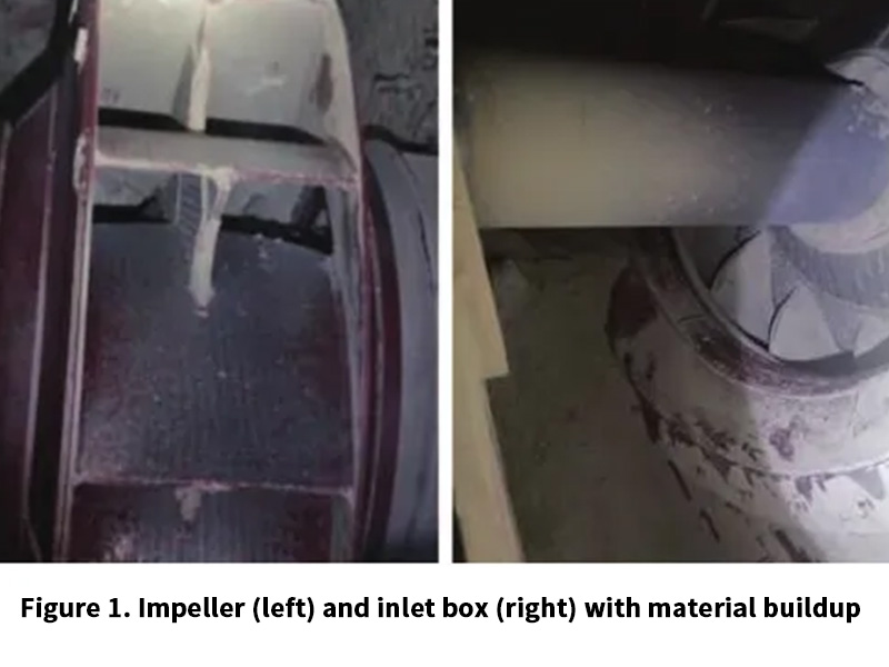
(3) Opening the inspection door revealed obvious dust accumulation on the back of the impeller and accumulated material at the bottom of the inlet box. See Figure 1 (left shows the impeller dust accumulation, right shows the inlet box material accumulation).
2 Cause Analysis
To address the above problems, this article analyzes from aspects such as the fan’s structure, the dust content in the airflow, the flow velocity, and the properties of the material.
2.1 Fan Structure
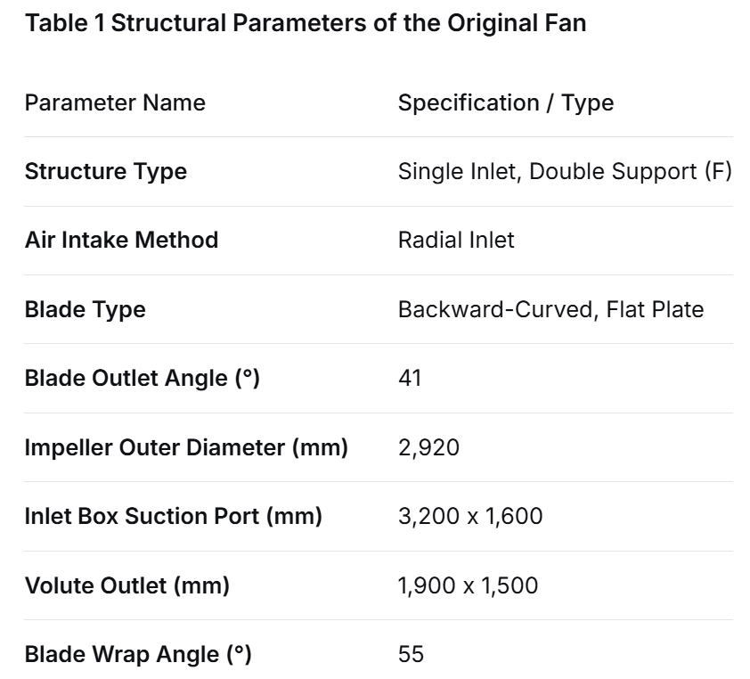
In terms of design, the fan’s energy efficiency indicator is the primary concern. Usually, the best blade placement angle, wrap angle, and relevant cross-sectional dimensions are selected based on given parameters and the matching speed. However, extreme operating conditions that may occur after the system is put into operation are not fully anticipated. The relevant structural parameters of this circulating fan are shown in Table 1.
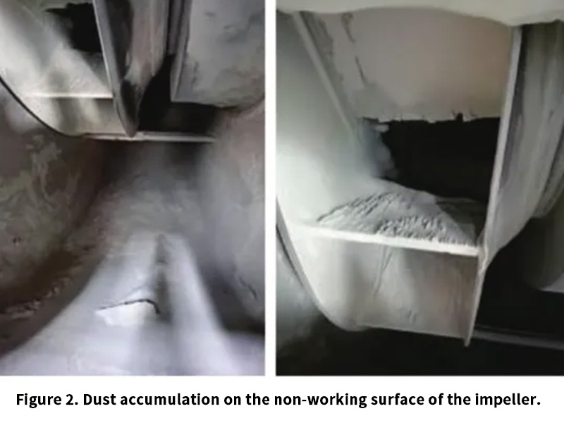
Theoretically, when a fan conveys dust-laden gas, a certain low-pressure vortex area forms on the back of the impeller blades. This is the theoretical dust accumulation area. Research shows that by analyzing the gas flow field in the impeller and the movement patterns of dust, dust mainly adheres to the non-working surface of the blades. It especially adheres to the leading and trailing edge areas of the blade non-working surface (see Figure 2). Therefore, selecting which fan and which blade structure to use in different applications is particularly important. Different blade structures exhibit different performance characteristics. Airfoil blades and flat plate blades each have their own suitable operating conditions.
2.1.1 Airfoil Type
Influenced positively by the airfoil lift, the design efficiency of airfoil blades is 4%~6% higher than that of flat plate blades. However, their structure is hollow. Under high dust concentration conditions, if the working surface is worn through by dust, dust entering the hollow cavity quickly causes loss of dynamic balance. Furthermore, this damage is irreparable. Although airfoil fans have great efficiency advantages, their prerequisite for application in high dust concentration situations is that wear resistance must be ensured. Therefore, circulating fans in the cement industry generally avoid using the airfoil type.
2.1.2 Flat Plate Type
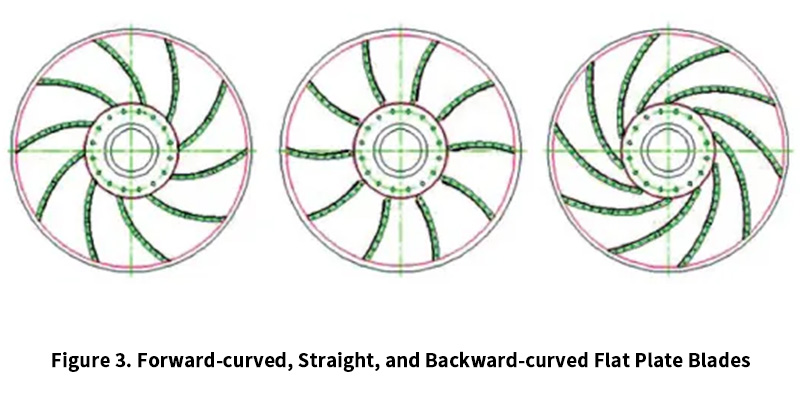
Flat plate blades can be broadly divided into forward-curved, straight, and backward-curved types based on the degree of blade curvature (see Figure 3, from left to right: forward-curved, straight, backward-curved). Because the inlet/outlet placement angles, blade length, and curvature of these three forms are different, their efficiency values also differ. Although the efficiency of flat plate blades is not advantageous compared to airfoil blades, flat plate blades have irreplaceable advantages in wear resistance, on-site repair, and maintaining dynamic balance. They are the preferred blade type for high dust concentration conditions.
(1) Forward-curved: Low efficiency (60%~75%). Blades are designed according to a single arc shape. Generally used for higher pressures, speed not less than 1480 r/min. Dust accumulation is very high.
(2) Straight: Low efficiency (65%~73%). The blade profile is basically a straight line. Dust accumulation is less.
(3) Backward-curved: High efficiency (80%~84%). The longest blades and largest wrap angle are the main reasons for its highest efficiency among flat plate blades. However, because it has the strongest carrying effect on dust-laden gas and the widest contact area, essentially, if a fan with this type of blade is used in conditions where dust concentration exceeds 120 g/Nm³ and humidity is high or temperature is extremely high, there is definitely a risk of dust accumulation, meaning it is relatively prone to dust accumulation.
Additionally, if the straight blade’s outlet placement angle develops to 90°, it becomes a radial blade. Its efficiency is the lowest (58%~68%). The blade profile is basically a straight line. It throws dust out radially through centrifugal force. Dust accumulation is very little.
In summary, the higher the efficiency value, the more dust accumulation; the lower the efficiency value, the less dust accumulation.
2.2 Dust Content in Airflow
Generally speaking, as equipment within the system, a fan should not accumulate large amounts of dust in a short time. If a large amount of dust appears on the fan impeller and the bottom of the inlet box in a very short time, it indicates that the dust content in the gas entering the fan is high. The degree of dust deposition on the back of the fan blades is closely related to the structure type and dust removal efficiency of the dust collector in front of the fan. Cement mill circulating fans often use cyclone dust collector designs at the front end. The dust removal efficiency of the cyclone directly affects the dust concentration at the inlet of the circulating fan. If severe dust accumulation is found in the circulating fan, inspection should first be conducted sequentially from the circulating fan inlet to the mill outlet process section. Items such as the opening of regulating valves on the pipeline, internal dust accumulation in the cyclone and outlet air velocity, operation of the discharge lock, internal dust accumulation in the V-separator, etc., should be checked one by one. This avoids abnormal increases in system airflow dust content due to problems with the above process equipment.
2.3 Airflow Velocity
Flow velocity has a significant impact on the formation of deposits because, as the flow velocity increases, the impact force and separation effect of the airflow increase. When the airflow changes direction in the impeller, clay dust particles separate from the main flow, impact the impeller at high speed, and adhere to it. The flow velocity in the fan’s inlet box cannot be too low. Otherwise, a large amount of dust easily accumulates at the bottom of the inlet box, worsening the fan’s operating condition. For example, a cement mill circulating fan may have difficulty starting due to dust accumulation in the inlet box. When airflow passes through the fan inlet box, the flow passage cross-sectional area gradually contracts in the meridional section and the plane perpendicular to the shaft. A moderate acceleration should be maintained. Calculation shows the original fan inlet box inlet velocity Vs=18.4 m/s. Under these conditions, this velocity is considered low.
2.4 Material Properties
Deposits usually form as mixtures of dust. Sampling tests show that typically, clay and alkali metal compounds can promote the formation of deposits. Viscous dust particles impact the leading edge of the blade at high speed, forming deposits (often from clay) into hard, firm, non-volatile lumps. The higher the moisture content of the dust particles in the fan inlet airflow, the faster the accumulation on the blades will be. At the same time, when the gas contains highly viscous particles, the dust accumulation rate on the blades increases and the degree of accumulation worsens.
3 Solutions
As an important air pulling (or blowing) device in cement production, some systems, due to process design and local materials, inevitably cause some fans to experience internal dust accumulation. Based on the above analysis, the following solutions are proposed for the dust accumulation problem in cement mill circulating fans.
3.1 Correctly Select the Fan
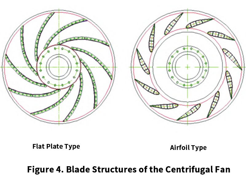
Centrifugal fans commonly used in cement production can be structurally divided into: double suction double support, single suction double support, and single suction overhung types. In terms of blade structure, they can be divided into: flat plate type and airfoil type (see Figure 4). For dust-laden systems in cement plants, selecting different structural types of fans and blade structures will affect the actual usage effect to a certain extent. Regarding fan selection, comprehensive consideration is needed:
(1) Stability: Double suction double support > Single suction double support > Overhung; Efficiency: Airfoil > Flat plate;
(2) Dust accumulation: Flat plate > Airfoil; Wear resistance: Flat plate (hardfacing/wear-resistant plate) > Airfoil;
(3) Dust content: The selection of fans for process sections with dust (general design value 80~120 g/Nm³) should follow the principles of little/no dust accumulation, small vibration value, good stability, and relatively high efficiency. In current mainstream designs, double suction/single suction double support should be the first choice, and the blade type should preferably be flat plate. Therefore, from Table 1, the structural type and blade type of this system’s circulating fan can meet the on-site usage requirements.
3.2 Increase Inlet Box Velocity
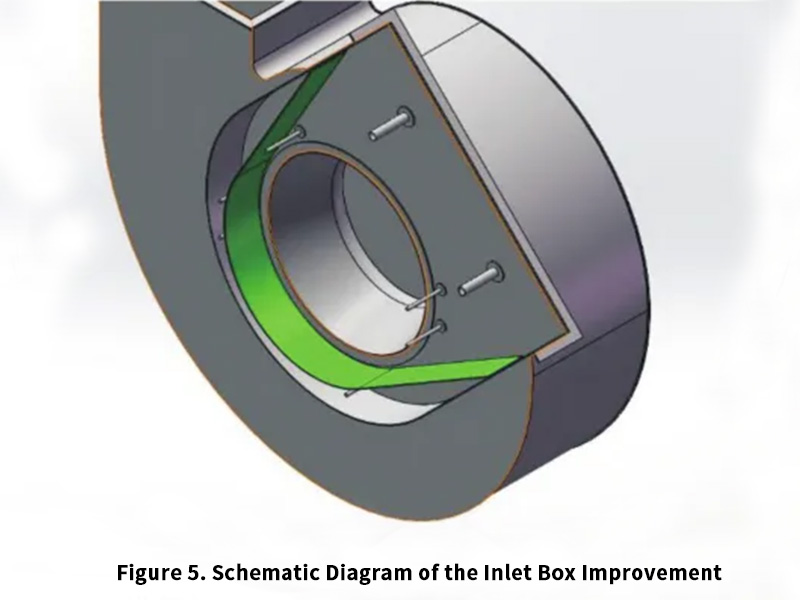
This circulating fan has a radial inlet box structure. The gas flow direction is first radial then axial, creating a 90° turn. Especially at the bottom of the inlet box, a certain vortex area forms. The flow velocity in this circulating fan’s inlet box is low. In future designs for such fans, it can be increased to above 24 m/s. Based on the above analysis, for this circulating fan, an inclined plate can be added inside the inlet box. This rapidly reduces the cross-sectional area at the bottom inside the inlet box, quickly increases the velocity of the dust-laden medium, making it easier for the dust to be carried into the casing interior and then carried out by the rotating impeller. The green plate in Figure 5 shows the internally added inclined plate.
3.3 Reduce Fan Operating Speed
When dust accumulates on the impeller, under the premise of the same dust content and accumulation, the higher the impeller speed, the greater the vibration value caused by the unbalance. Combined with the actual operation requirements of cement plants, when the speed is greater than 1000 r/min, a vibration value ≥6.3 mm/s triggers a bearing vibration alarm, and a vibration value ≥11 mm/s triggers a bearing vibration trip. Therefore, from the perspective of reducing the allowable unbalance at the rotor, the lower the operating speed of a dust-laden fan, the greater the allowable unbalance of its impeller. For some manufacturers, if no better solutions are available during fan design and selection, appropriately reducing the design speed of the fan’s matching motor can be considered. For fans running at power frequency, adding a speed control device can be considered appropriately. The operating frequency of this circulating fan is about 47 Hz. By changing the impeller’s aerodynamic model to increase impeller output and then reducing the fan operating frequency to below 43 Hz, the operational stability of the fan can be improved.
3.4 Change the Blade Profile Design Method
The basic premise of improvement measures is to balance efficiency and dust accumulation risk. The design of the impeller profile needs focused attention. When the airflow’s angle of repose is consistent with the impeller blade inlet angle, the aerodynamic effect of the airflow is best. Furthermore, when the blade outlet angle increases, the dust adhesion rate decreases. By increasing the inlet and outlet angles of the impeller blades, the difficulty for dust to adhere to the non-working surface of the impeller blades can be increased, making the blade non-working surface itself less prone to dust accumulation. Specific improvement measures are: reduce the blade wrap angle to 40°~45°, increase the blade outlet placement angle to 44°~47°. Using a logarithmic spiral to redesign the blade profile based on performance requirements can effectively reduce the risk of fan impeller dust accumulation without significantly reducing efficiency.
Taking the 710 kW motor matched with this circulating fan as an example, if the fan’s own operating efficiency increases by 10%, it essentially means the power saving rate under the same air volume and pressure is approximately 10%. It can be roughly estimated that the fan saves 71 kWh per hour. Calculated based on 5000 hours of annual operation, the annual power saving = hourly saving × annual operation time = 71 × 5000 = 355,000 kWh. Therefore, the design of the new blade profile needs to balance stability and efficiency value. Impeller design is crucial for cement mill circulating fans used in high dust concentration conditions.
3.5 Strengthen Control of Material Moisture
This production line mainly produces P·O 42.5 grade Portland cement. Desulfurization gypsum accounts for 5%~8%, limestone moisture is 1.3%~1.8%, desulfurization gypsum moisture is 12%~15%. Both the gypsum proportion and its moisture content are relatively high. The high proportion of desulfurization gypsum and its high moisture content are the main factors causing high material moisture entering the fan. The comprehensive external moisture of desulfurization gypsum can be controlled below 9% through sun-drying for a certain period. This reduces the stickiness of the dust in the gas, thereby reducing the dust accumulation rate on the blades.
4 Conclusion
In summary, the performance of centrifugal fans is affected by multiple parameters interacting. Structural type, blade profile design, and speed matching all have certain impacts on field use. When a fan vibrates frequently due to dust accumulation, investigation needs to be conducted from multiple aspects simultaneously. Fan operation is greatly influenced by system layout, process operation, material physical and chemical characteristics, etc. For cement mill circulating fans, airfoil impellers should preferably not be used. When using flat plate impellers, besides optimizing the fan inlet box and reducing operating speed, the optimized design of the impeller also needs to balance fan efficiency and dust accumulation risk. The operating state of the system, the design of the centrifugal fan, and the matching degree with the process system all affect the system’s power consumption and production output indicators. As equipment manufacturers, applying high-efficiency centrifugal fans to energy saving and consumption reduction in the cement industry, better serving enterprises, reducing costs and increasing efficiency, and tapping potential, is a goal worth pursuing continuously.