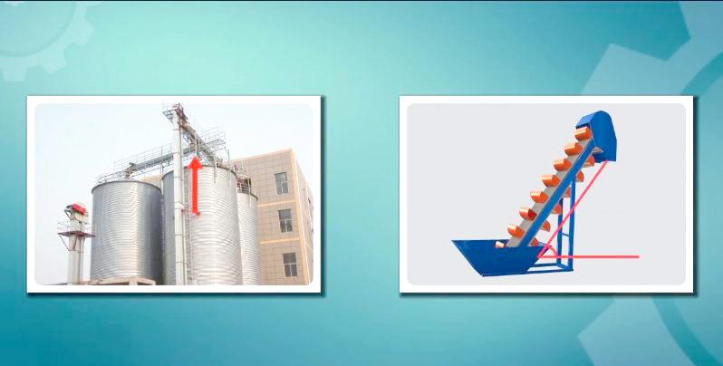
A screw conveyor is one of the most commonly used pieces of equipment for the continuous conveying of powdered materials.
Its advantages include a simple structure; consequently, besides the transmission device, there are no other rotating parts outside the machine casing. Furthermore, it occupies a small area, is easy to seal, and is simple to manage, maintain, and operate. Additionally, it facilitates loading and unloading at multiple points.
However, screw conveyors also have disadvantages. Primarily, they exhibit high operational resistance due to friction between the casing and the screw blade, between the screw surface and the material, and between the casing and the material. Therefore, their power consumption is generally higher than other conveyors, and component wear is relatively rapid. As a result, they are unsuitable for conveying large, blocky, or highly abrasive materials. Moreover, due to significant friction, the conveying process considerably pulverizes the material; thus, they are not recommended for materials where specific particle size must be preserved. Finally, because of the substantial wear on components, this equipment is only used for low to medium productivity rates (up to 100 m³/h), and the conveying distance should not be too long.
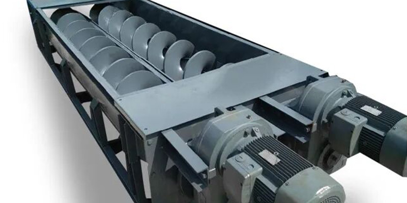
I. Structure
A screw conveyor mainly consists of a screw shaft, a trough, and a drive assembly. The lower part of the trough is semi-circular, and the screw shaft is placed longitudinally inside it. When the screw shaft rotates, the material, due to its own weight and the friction against the trough walls, does not rotate with the screw. Consequently, the axial thrust generated by the rotation of the screw shaft acts directly on the material, pushing it forward. This action causes the material to slide axially. The axial movement of the material resembles a nut on a screw: if the nut is prevented from rotating, the rotation of the screw translates the nut along it. Similarly, the material is pushed in one direction during the screw’s rotation until it is discharged at the outlet.
1.1 Screw
The screw consists of a shaft and blades attached to it. The shaft can be either solid or a hollow pipe. Notably, for the same strength, a pipe shaft is lighter than a solid shaft and easier to connect, making it more commonly used. Manufacturers typically make pipe shafts from extra-thick seamless steel tubing, with diameters generally between 50 and 100 mm. Each shaft section is usually under 3 meters long to facilitate sectional installation.
Screw blades are designated as either left-handed or right-handed. The method for determining the handiness is shown in the figure below. The direction of material conveyance is determined by both the blade direction and the rotational direction of the screw. For a right-handed screw, rotation in direction ‘n’ pushes material towards the discharge outlet; conversely, reverse rotation pushes material in direction ‘v1’. A left-handed screw pushes material in the opposite directions.
Depending on the properties of the material being conveyed, screws come in various shapes. For instance, when conveying dry, small-particle materials, a full-blade screw is used. Conversely, for lumpy or moist, sticky materials, a ribbon screw is suitable. Furthermore, when conveying compressible materials, a paddle or cut-flight screw is employed. Paddle or cut-flight screws also serve additional functions like mixing, blending, and aerating the material.
Blades are typically pressed from 3-8 mm thick steel plates and then welded onto the shaft. However, for highly abrasive or very sticky materials, blades are made from rolled flat steel or cast iron.
1.2 Trough
The trough comprises head, intermediate, and tail sections, bolted together. Each standard section is 1-3 meters long and is usually made from 3-6 mm thick steel plates. A removable cover plate seals the top of the trough. The inlet is located on this cover, while the outlet is at the bottom of the trough. Sometimes, multiple discharge openings are provided along the length for intermediate discharge. Gates are fitted at both inlet and outlet ports. Additionally, the cover features inspection ports for monitoring material flow. The trough is mounted on supports, made of cast iron or welded steel, which are then secured to the ground. The clearance between the screw and the trough is 5-15 mm. Excessively large clearance reduces conveying efficiency, while overly small clearance increases operational resistance and can even cause damage or breakage to the blades and shaft.
1.3 Bearings
The screw is supported within the trough by end bearings and intermediate bearings. The head and tail ends of the screw shaft are supported by a thrust bearing and a radial bearing, respectively. The thrust bearing, typically a tapered roller type, absorbs the axial force generated during conveying. Placing it in the head section subjects the screw shaft primarily to tension, which is a favorable stress state. This thrust bearing is mounted on the end plate of the head section and also acts as a support for the screw shaft. The tail section differs mainly by having a double-row self-aligning ball bearing or a plain bearing on its end plate.
When the conveyor length exceeds 3-4 meters, intermediate bearings are installed in addition to the end bearings to support part of the screw shaft’s weight and operational forces. These intermediate bearings are suspended from crossbars, which are fixed to the trough flanges or reinforcing angles, hence they are called suspended or hanger bearings.
Because the screw flight is interrupted at the hanger bearing, material tends to accumulate there. Therefore, hanger bearings should be as compact as possible and not spaced too closely; generally, one is installed every 2-3 meters. Standard screw sections are 2-3 meters long. To connect several standard sections to the required total length, coupling shafts are used, which are supported by these hanger bearings. Both the coupling shaft and the bearing bush are susceptible to wear. Bushings are often made of wear-resistant cast iron or Babbitt metal. The bearings also include sealing and lubrication devices.
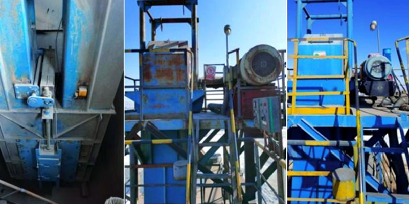
1.4 Drive Assembly
There are two main forms of drive assemblies: First, a motor and reducer connected by an elastic coupling, with the reducer and screw shaft typically linked by a floating coupling. Second, a direct drive using a gearmotor, eliminating the separate reducer. When planning the layout, it is best to position the drive assembly and the discharge outlet together at the head section, as this results in more favorable force distribution on the screw shaft.
II. Application Overview
Currently, the GX series and LS series are common screw conveyor models. The GX series offers seven specifications with screw diameters from 150 to 600 mm. Their lengths generally range from 3 to 70 meters, adjustable in 0.5 meter increments. Individual screw shaft sections come in four lengths: 1500 mm, 2000 mm, 2500 mm, and 3000 mm, allowing combination based on the required conveying distance. Drive methods include single-end drive and double-end drive. The transmission can use a motor-reducer combination or a gearmotor.
The main differences between the LS series and the GX series are as follows:
-
The head and tail bearings are relocated outside the casing.
-
The intermediate hanger bearing can use either roller or plain bushings (interchangeable). Bushings for plain bearings include cast copper, wear-resistant alloy cast iron, and copper-based graphite. Seals, made from materials like nylon or PTFE, offer low resistance, good sealing, and high wear resistance.
-
A cleaning device is included at the discharge end.
-
Inlet and outlet arrangements are more flexible.
-
The machine features low noise and high adaptability.
Application Characteristics: The application characteristics of the LS and GX series screw conveyors are largely consistent, summarized as follows:
-
Due to the small effective cross-sectional area inside the casing, they are unsuitable for large lump materials. However, they can convey various powdered and small granular materials.
-
They are not suitable for materials prone to degradation, high stickiness, or agglomeration, as these can adhere to the screw, causing blockages and operational failure.
-
Due to high power consumption, the conveying length is generally limited to less than 70 meters. For distances over 35 meters, double-end drive is recommended.
-
They can be used for horizontal or inclined conveyance, but the inclination angle is typically limited to less than 20°, and conveyance is unidirectional.
-
The operating ambient temperature should range from -20°C to 50°C, and the temperature of the conveyed material should be below 200°C.
III. Specification Designations
(1) By Drive Method:
-
C1 Design: Single-end drive. The thrust bearing has an extended shaft end for connecting the drive assembly.
-
C2 Design: Double-end drive. Both ends have extended shaft ends, allowing the conveyor to be driven from both sides simultaneously.
(2) By Screw Type:
-
B1 Design: Full-blade screw with a pitch equal to 0.8 times the screw diameter.
-
B2 Design: Ribbon screw with a pitch equal to the screw diameter.
(3) By Intermediate Hanger Bearing Material:
-
M1 Design: Intermediate hanger bearing bushings made of Babbitt alloy (an alloy of copper, antimony, and tin). For the LS series, this corresponds to a roller hanger bearing.
-
M2 Design: Intermediate hanger bearing bushings made of wear-resistant cast iron. For the LS series, this corresponds to a plain hanger bearing.
(4) By Drive Assembly Orientation:
-
Right-hand Assembly : Standing at the motor’s tail and looking forward, the reducer’s low-speed shaft is on the right side of the motor.
-
Left-hand Assembly : Standing at the motor’s tail and looking forward, the reducer’s low-speed shaft is on the left side of the motor.
IV. Screw Conveyor Specification Format
Specifications are represented in the following format:
Nominal Diameter × Nominal Length – Screw Type – Drive Method – Bushing Material
Example 1: A GX series screw conveyor with a nominal diameter of 600 mm, nominal length of 22 m, full-blade screw (B1), single-end drive (C1), and Babbitt alloy bushings (M1) is designated as:
GX600×22-B1-C1-M1
Example 2: An LS series screw conveyor with a nominal diameter of 600 mm, nominal length of 22 m, full-blade screw, single-end drive, plain hanger bearings (M2), and a rotational speed of 50 r/min is designated as:
LS600×22×50-M2